Dr. Jonas Helming is CEO of EclipseSource as well as consultant, trainer and software engineer. His focus is on web-based tools, IDEs, and tailored AI assistance in tools …
Eclipse 4 (e4) Tutorial Part 1
May 10, 2012 | 12 min ReadThis tutorial series introduces the new concepts in the Eclipse 4 Application Platform, aka RCP 2.0. While some projects still use the compatibility layer, it is worthwhile to look at and benefit from the new concepts. This tutorial and all other parts of the series are available as a downloadable PDF.
We will start with the foundation of every Eclipse 4 application, the application model. In this first part, we give an overview of the most important elements of this model to define the layout of your application. Subsequently, we to introduce the different options for modifying this model.
Application Model vs. Views
In Eclipse 4, the workbench is defined in the so-called Application Model. This includes windows, views, perspectives, menu contributions, handlers and key bindings. Using the model you define the general design or “skeleton” of your application. Defining a model doesn’t already require that you implement the single components. For example, you can add a view to the model without implementing its contents. To show the resulting separation between the general workbench design and the implementation of single parts, I will not show any SWT or JavaFX code in this section. Instead, we’ll focus on the model and how to connect the model to code.
Windows, Parts and PartContainers
The cornerstones of the application model are windows, parts and part containers. Contrary to the eclipse 3.x platform, e4 has combined views and editors into the concept of Parts, which represent views inside a window. If you add a part in the model, you can later connect it to your implementation of the selected view.
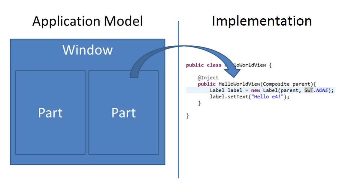 The Parts of an application model are connected later to their implementations
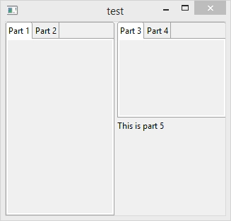
As parts cannot exist on their own, they are always contained in PartContainers. Those PartContainers create an application layout. Besides windows, there are two elements which can contain Parts: PartSashes and PartStacks. A PartSash will arrange contained elements either vertically or horizontally. A PartStack adds an area, where the contained elements are stacked behind each other, only one element is shown on top. PartSash and PartStack can contain each other to create any kind of layout within a window. The following example shows an example layout. The left side shows the respective Application Model, the right side the rendered result. The first PartStack is set to “horizontal” orientation, the second one to “vertical”. Please note, that part 5 would actually not be visible, if parts are not contained in PartStacks, their label is not shown. For the example, we added an implementation for part 5, which shows a label to make it identifiable in the screenshot. All other parts do not have any implementation, yet, so you can design your application without already thinking about the contents of views. In the following section, we describe how to create a first application model using Windows, PartsSashes, PartStacks and Parts, only.
Installation
The most convenient way to modify an Application Model is the e4 Model Editor, which will be described in the following. Starting from Mars, it is already part of some Eclipse Packages (Eclipse for RCP Developers, Eclipse Modeling Tools and Eclipse for Committers). For carrying on with the tasks from this tutorial, we recommend you to download the latest version of “Eclipse for RCP developers” from here: https://eclipse.org/downloads/.
Creating an e4 Application
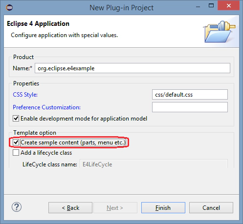
The easiest way to get started is to use a template to create a new e4 application. This will create a bundle containing all necessary artefacts for an Eclipse 4 Application including the Application Model. To create such a project, choose the “Eclipse 4 Application Project” entry within the “New Project” wizard. Give a name to your project on the first page of the wizard and select the “Create sample content” checkbox on the last page. This option will already fill the template Application Model with some elements.
Before we have a look at the Application Model, we will start the template application once. For this purpose, the template wizard creates a product definition and you can start the application simply by starting this product. To do so, open the *.product file and click on run or debug in the upper right corner of the editor.
![]() Click here to start the product.
Click here to start the product.
As you can see below, the generated template application already contains a window, two menus, a toolbar and a PartStack and a Part within it. In fact, the model also already contains a PerspectiveStack and a perspective, but this is currently not visible.
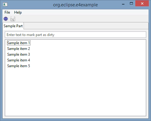
The e4 Model Editor
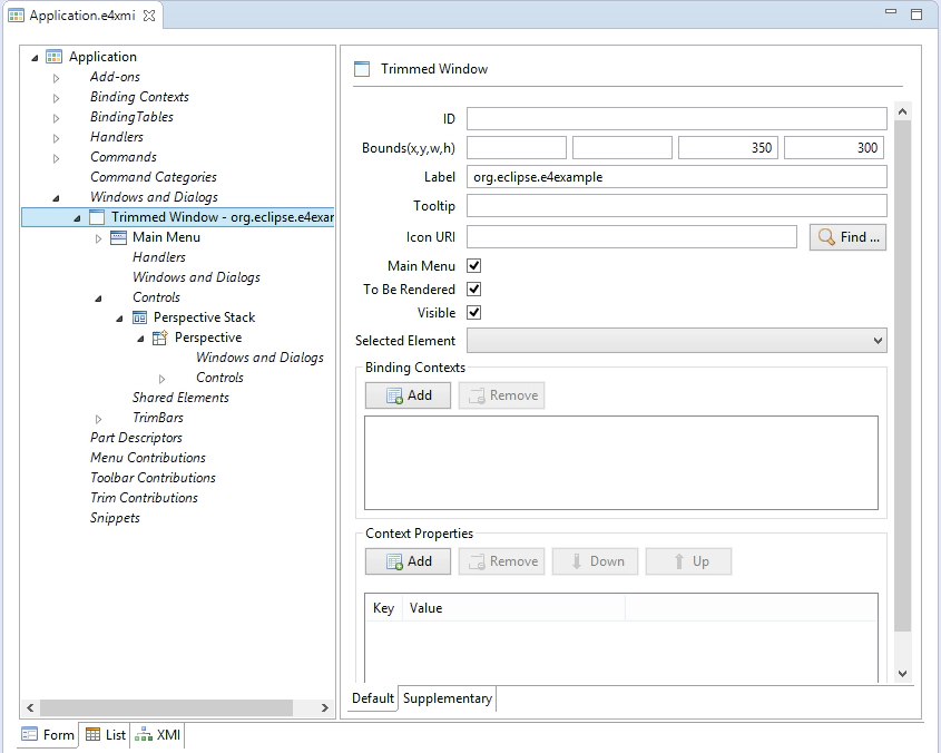
To modify the application model and therefore the layout of your application, Eclipse provides the e4 Model Editor. You can open it by double clicking the Application.e4xmi located in the root level of the project.
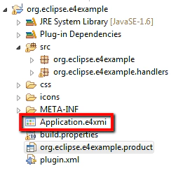
Open the application model to modify the workbench
On the left side you see a tree showing the complete contents of the model. Tree nodes with icons are model elements, e.g. the root element “Application”. in the level below those elements you find tree nodes without icons. Those are like folders and structure the elements, which are contained by a parent elements. As an example, the application has a folder called “Windows and Dialogs”. By expanding this node, you see all windows and dialogs, which are contained by the application. By selecting any element in the tree, a detailed view will be opened on the right side, allowing you to modify the properties of that element. If you select a folder, the right side will present a list of elements which are contained in that folder.
The top-level elements of an application are usually one or more windows that you can find in the application model in the folder “Windows and Dialogs”. The template project already contains a TrimmedWindow. By selecting this element you can, for instance, modify the size of this window, in the “Bounds” fields. Check the result by restarting the application.
With a right click in the on folders in the tree, new elements can be added within those folders. Using the delete action in the right click menue of an element, you can remove them. As an example, you can remove the existing PerspectiveStack and just add a single Part instead. To do so, you need to expand the “Controls” item of the Trimmed Window in the Application tree. After a restart of the application, you will notice that the main area of the application does not have a border anymore. However, the new part isn’t visible, as it show no tab anymore. Tabs of Parts are only visible, if parts are contained in PartStacks. Try to add a PartStack as a child element of the TrimmedWindow and move the part in it. Adapt the label property of the Part, restart the application and check the result.
Model Spy (Live Editing)
Eclipse allows you to define the workbench using the application model even without providing implementations. However, this is sometimes hard to work with, because empty Parts are often hard to identify. To resolve this, there is a special version of the Model Editor called Model Spy. It allows you to access the application model of a running application, modify it and highlight selected components. The Model Spy is not yet part of the standard Eclipse Packages, it can be installed from the e4 update site.
To enable the Model Spy you need to start an additional plugin along with your application. Please note that you typically do not want to make the Model Spy a permanent part of your application, so it should not be added to the product. Instead, open the run configuration and add the bundle “” to it. Additionally click on “Add required” to include the required dependencies. A run configuration should have been created for you when you first started the product.
In the running application you can start the live editor via ALT+SHIFT+F9. This editor works exactly like the editor in your IDE, however, it directly accesses the application model of the running application. If you, for instance, open the TrimmedWindow in the editor and change its size or position, the changes are directly applied in the running application.

The live editor is not only capable of modifying elements, you can even add new ones. As an example, if you add a new window to the application model (right-click on the folder “Windows and Dialogs”), a new window will be opened in the application. To maintain an overview of which components are visible in the application, these components can be colored. By right-clicking an element in the live editor, e.g. the TrimBar and selecting “Show Control”, the control will be colored in red in the running application.

Elements of the application models can be colored in the running application.
Using this feature, one can easily visualize changes within the application model. This is especially useful for elements which are not directly visible in the UI. As an example, if you add a new Part in a Window (without a containing PartStack), it will not be visible without coloring, as it does not have any content yet.
If you use the live editor to change the application model, the changes will only be reflected in the running application. To transfer them into the deployable application, you can copy the modified version of the model using the tab “XMI” and copy it into the model available in your IDE.
Development Model vs. Runtime Model
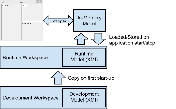
So far, we have created and modified the Application Model in our IDE, meaning during development time. This was done by using the e4 Model Editor, the resulting model was persisted in the Application.e4xmi file. When a e4 application is started, this file is deployed along with the containing bundle. When an application is started, a copy of this file will be placed in the workspace of the running application. From there on, this copy will always store the latest state of the running application, e.g. the arrangement of Parts. Consequently, when re-starting the application from within the IDE, this copy will not be overridden by default. While developing an application, you typically want the new state of the Application Model, e.g. when you have added some new elements. You can achieve this by either deleting the workspace of the running application completely or by adding the command parameter “-clearPersistedState” to the product/run configuration. Please note that the product we have created before using the e4 wizard already contains this parameter (see the .product file on the tab “Launching”).
The default e4 application de-serializes this file and creates an in-memory representation of it. A rendering component interprets this model and creates the workbench describe by it, i.e. windows, parts, etc. If the application is started again with a adapted model, this will be reflected in the UI. Even more, the application model can even be changed at runtime using it’s API, e.g. the label of a window can be changed or new parts can be created. The rendering component is listening to all changes to the model at runtime and will reflect those changes in the running application. We will describe in the following section how to access the model at runtime.
Programmatic Access to the Application Model
During runtime, there is a Java Object for every element of the deserialized Application Model. Technically, those objects are EMF objects (EObjects), so the API is very familiar to anyone who has worked with EMF before. By using this API you can create or modify parts of the application programmatically, like, for example, reacting to a user action. To test this in the template application created before, you can take a look at one of the existing handlers, such as the class OpenHandler. As you can see in this handler, there is a method execute() marked with the annotation @Execute, which will be called if the connected ToolItem is clicked by the user.
Dependency injection allows the programmer to easily define which parameters are needed within this method. We will go into detail about dependency injection and the implementation of handlers later, for now, we will just use the existing handler to execute some example code, which modifies the Application Model at runtime.
In the following code example, the method requires the application istself as parameter, so it will be injected by the framework. Please note, that the Java Objects (more precisely their interfaces) to access the Application Model at runtime are all prefixed with a “M”. As an example, you can access a Window using the interface “MWindow” or a Part using the interface “MPart”.
In the following code example, a new window is created. To add this new window into the application, the application is required as a parameter. Using the API, the window is sized, a new part is added into the window and the window is added to the application. By adding the window to the application, it is opened in the running application. Start the application and press the toolbar button to check the result.
@ Execute
public void execute(MApplication application) {
MWindow mWindow = MBasicFactory.INSTANCE.createTrimmedWindow();
mWindow.setHeight(200);
mWindow.setWidth(400);
mWindow.getChildren().add(MBasicFactory.INSTANCE.createPart());
application.getChildren().add(mWindow);
}
Conclusion
The e4 application models allows you to define the general design of an application in a consistent way, without implementing single parts in advance. We described different methods to modify the application model, including how to modify the model during runtime using the live editor or the API. At this point we have only created placeholders in the application. The next part of this series describes how to connect the application model with the implementation of UI components, that is, how to create the connection between a part and the implementation of a view filling this part.
This tutorial and all other parts of the series are available as a downloadable PDF or as links below:
Part 1: Introduction to Eclipse 4
Part 2: Application Model and Views
Part 3: Extending existing models
Part 7: Soft migration from Eclipse 3.x
Appendix: Eclipse 3.x vs. Eclipse 4 - Which Platform to use
For more information, contact us:
Jonas Helming and Maximilian Koegel
EclipseSource Munich leads
Author: Jonas Helming
