Jonas Helming, Maximilian Koegel and Philip Langer co-lead EclipseSource. They work as consultants and software engineers for building web-based and desktop-based tools. …
EMF Forms: The Right Level of Abstraction
June 6, 2014 | 10 min ReadIn my last blog post, I started to describe the framework EMF Forms in more detail and compared it to manual UI programming. To recap, EMF Forms is a framework for efficiently creating form-based user interfaces. Instead of programming form-based UIs manually, they can be described by a simple view model. This model is then interpreted by a customizable rendering component to display the actual UI. A general introduction to the framework can be found in this tutorial and on the website. Of course, you should expect that a framework that specializes in creating a form-based user interface is more efficient in the development of such – especially in comparison to manual solutions. In this post, I will focus on a less obvious advantage of EMF Forms: the level of abstraction it lets you achieve.
By describing a form-based UI in a model instead of in source code, not only is the level of effort lower, but at the same time the level of abstraction of the description is significantly increased. This fact brings two major benefits. Firstly, the definition of the UI (in the model) is much closer to a specification that a user would give as a requirement. Secondly, the concept of an independent rendering component offers a high degree of flexibility. This article discusses both aspects on the basis of two concrete examples. We first examine the smallest unit of a form-based user interface, a single control, and then the arrangement of these controls in a structure, i.e., in an appropriate layout.
The Smallest Unit
Input fields (also called widgets or controls) form the smallest part of a form-based user interface. They display the data and allow the modification of attributes. Many form-based UIs consist essentially of a combination of simple standard widgets such as text fields for string attributes or drop-down lists for enumerations. Even at the level of input fields, the difference between the manual programming and a model-based approach is very obvious and will be shown concretely in the following sections. For example, the following given requirement shall be implemented in a form-based user interface:
“The attribute firstName of the entity User can be viewed and edited in the form-based interface.” When implementing the requirement, some implicit assumptions must be made. They can usually be taken for granted or easily be derived from the data model:
- The attribute is shown as a text field
- The name of the attribute is displayed as a label to the left of the text box
- The text box always shows the current value of the data entity and is therefore bound to it
The following code example shows a possible implementation of the requirement as well as the additional assumptions in SWT using Eclipse Data Binding. First, a two-column grid is prepared. Next, the two elements (label and text field) are created, and, finally, the text box is bound to the data object:
GridLayoutFactory.fillDefaults().numColumns(2).applyTo(main);
GridDataFactory.fillDefaults().grab(true, false).align(SWT.FILL, SWT.BEGINNING).applyTo(main);

Label label = new Label(parent, SWT.NONE);
Label.setText(“First name:”);
Text textField = new Text(parent, SWT.NONE);

ISWTObservableValue observedTextField = SWTObservables.observeText(textField);
IObservableValue observedValue = EMFObservables.observeValue(user, TaskPackage.eINSTANCE.getUser_FirstName());
getDataBindingContext().bindValue(observedTextField, observedValue);
It immediately catches the eye how much code has to be written to actually implement this very simple example. The code is even hard to map to the original requirement. This is not least because the SWT is not dedicated to the implementation of a form-based user interface. Thus, the implicit assumptions described above must be fully implemented.
When using the view model of EMF Forms, the situation is different. In the simplest cases, only the absolute minimum information needs to be specified explicitly (see Figure 1). In addition to the existence of a view and the controls themselves, the only truly necessary information is the specific attribute from the data model that should be displayed in the control. For this purpose, the control holds a reference to the attribute in the data model, which should be bound to the control. In the example, this is the attribute firstName of the entity User.
Assumptions 1 to 3 as described above are initially made without additional information and therefore need not be specified explicitly. They can, if necessary, be adapted later simply and centrally.
Figure 1: A simple view model with only one control
The view model is now interpreted by a renderer to a concrete user interface. Both procedures (manual SWT code and view model) lead, in the end, to the same result, as shown in Figure 2.
Figure 2: The identical result of the example from manual programming and the use of EMF Forms
The Comparison
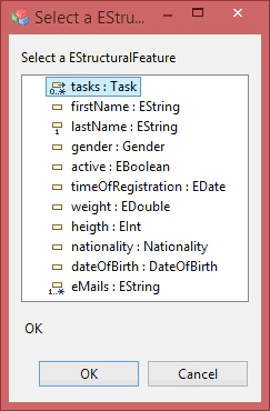
When comparing the model-based design interface with the manually written source code, it is immediately apparent that the model-based variant is much more concise and easier to read. It is also much closer to the original specification of the requirement. With the tooling offered by EMF Forms, even non-technical end users could specify such a control. Figure 3 shows the dialog that is used to select which attribute is displayed in a control.
Figure 3: EMF Forms offers tooling for the specification of a view model, for example to select the attribute of a control
The advantages described are actually no surprise since the model of EMF Forms certainly specializes in specifying form-based user interfaces. It thus provides, for example, the concept of control, while SWT operates on the level of labels and text boxes.
But better abstraction not only allows a more compact and simpler description of the interface, it also allows greater flexibility in the user interface’s design. In the case of EMF Forms, this is accomplished by a renderer that interprets the model. Without additional adjustments, the renderer included with EMF Forms automatically adheres to the corresponding assumptions (1 to 3 above). However, these assumptions could prove to be partially wrong or out of date, for example, at a later date. In the example of a control, it has been implicitly assumed that the label should be displayed to the left of the input field. Should this requirement change, for example, should the label not need to be displayed, this change would need to be adjusted manually in the UI at all relevant points. When using EMF Forms, only the renderer for the responsible controls needs to be adjusted in a single central location. So the overall appearance of the application can be customized very effectively with one line of code. Many of these general rendering properties used for controls, such as colors, can even be adapted without changing code in EMF Forms since they can be configured declaratively. If you do not want to apply such an adjustment to any control, the corresponding property in the view model for individual elements may be specifically specified. If you no longer want to display labels, EMF Forms supports this already in the view model and this can be adjusted via the setting shown in Figure 4.
Figure 4: The view model allows settings to influence the behavior of the renderer for individual elements different from standard such as the positioning of the label.
Categories
In a real form-based user interface, the controls will sooner or later be structured in a layout. Here, the difference in the procedure of manual UI programming and the use of a view model is even clearer. We describe this again using a sample requirement. For this, the example entity User gets three additional attributes:
- LastName (String)
- Gender (Enumeration)
- DateOfBirth (Date)
An example requirement for the structure of the user interface could now be as follows:
“The attribute FirstName and LastName, in the category “Public”, Gender and DateOfBirth should be shown in the category “Private”.
As with the first example requirement, an additional question must be answered:
- How will the structure element category be translated into a concrete UI layout?
Possible example variations could be
- Categories will be shown as a group with a border
- Categories will be navigable via a master-detail
- Categories are separate tabs
Unlike the first three assumptions, there is no really obvious, clear or implicit answer. This means that for manual programming a variant must be selected. Since the variants can be programmed in many different ways and there are many instances of such categories, any subsequent change in the variant would be expensive. Of course it is difficult to make such final decisions in the initial phase of a project, especially when you do not even know all the attributes to display.
When using EMF Forms, these decisions do not need to be made up front. The view model first allows the recording of the original requirements of a structure of the control (see Figure 5a.)
Figure 5a: A view model allows the structuring of attributes, such as in categories
Only the renderer is responsible for translating this structure into an actual UI. EMF Forms provides some variants, and your own variants can be added as desired. If EMF Forms provides the desired renderer already, the variant can be replaced with just a few mouse clicks. To extend the available renderers, you will need manual coding, but only at a central location for the adjusted renderer. So in the example, the representation of the interface is rendered simply by changing the variants in figure 5b.
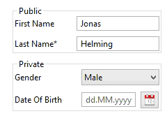
Categories as groups
Categories as master-detail
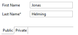
Categories as tabs
Figure 5b: View models can be rendered flexibly in different variations by changing the renderer
Such an evolution of different ways of representation is typical for projects in which the user interface is gaining more and more complexity over the development cycle. The model-based approach by EMF Forms provides the necessary flexibility. Such flexibility can, however, be valuable even without changes, for example, when a UI is to be displayed on devices that offer different screen sizes. While on the one hand, representation of all attributes with bordered groups on one page can be useful for a desktop, the attributes could be rendered as multiple pages on a mobile device.
Conclusion
This post compared the level of abstraction used in manual UI programming on one hand to the model-based approach such as form-based interfaces in EMF Forms on the other hand. The model-based approach is much closer to typical requirement definitions of a form-based UI. In practice, this fact even allows domain experts and non-developers to create or adapt view models. A good example is the classification of attributes into categories, which typically requires domain knowledge. The simple abstraction in the view model, the categorization by drag and drop, can also be performed by non-technical business users.
In addition, EMF Forms offers a higher flexibility compared to manual programming. The description of the form-based interface initially says nothing about the actual representation. Instead, the renderer is responsible for the representation. It can initially implement implicit requirements with a standard solution. If an adjustment is necessary, this can be adapted centrally at the renderer. If different versions need to be supported in parallel, appropriate settings can be provided in the view model and interpreted by the renderer. In terms of level of abstraction and flexibility, EMF Forms also offers clear advantages over the manual programming, and this is not surprising. EMF Forms was designed for exactly this purpose – form-based interfaces – while UI toolkits have to support any type of interface. Last but not least, the authors of the approach are, of course, also very connected to EMF Forms, so the article cannot be considered an objective comparison. However, we are interested in feedback, even if it’s negative. Only through feedback, especially of things that do not work as desired, or use cases in which a framework is not proven, are open source technologies continually developed and improved.
If you need support with embedding EMF Forms into your application, if you are interested in an evaluation or if you want to adapt the framework to your needs, we provide development support and training for these purposes.
EMF Forms is part of the Luna release.
Please visit this site to learn more about other EMF Forms features.


